WIRO
Long Slit Spectrograph
CuAr
Atlas available
here
Instrument pictures here
Instrument electronics here
The
long slit spectrograph is the third of a new generation of
instruments built for the Wyoming Infrared Observatory (WIRO). The
spectrograph was designed by Michael Pierce and Andy Monson from an
existing surplus spectrograph. Parts and machining were provided by
Steve Hodder and the A&S Machine Shop. James Weger developed the
electrical aspects of the spectrograph which was a great contribution
since the obsolete version had no existing electrical components. The
main goal of the instrument was to provide low resolution high
efficiency spectroscopy for faint targets such as AGN and also to
provide fast simple reduction for a number of targets such as stars,
where multiple targets can be observed in a relatively short amount
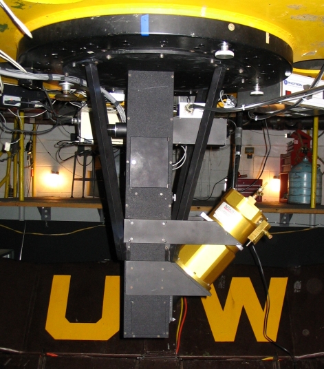
of time. The long slit spectrograph is mounted at cassegrain focus
(see figure to right) and uses the same Marconi detector housed in a
IR-Labs dewar which is also used in the WIRO-Spec and WIRO-Prime
instruments. The nominal position angle for the instrument is 0
degrees, however, it is mounted on an instrument rotator and can
achieve any desired position angle on the sky (manually). A PHOTRON
CuAr lamp is housed in the spectrograph to provide wavelength
calibration. An SBIG-ST-2000 camera is used for object acquisition and
guiding (25" field). This camera can also be used for imaging
(65" field) in UBVR, Halpha filters via an attached filter wheel.
Several gratings are available which can be swapped through an
access port on the spectrograph. One of the gratings operates in
second order so an order separation filter can be placed in the
system to eliminate first order contamination. The slit assembly
consists of a variable slit and dekker slide which can be manually
adjusted for desired performance.
Optical
Design
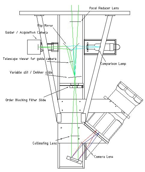 The
long slit spectrograph is mounted to the rear cell of the telescope
at cassegrain focus. Currently the secondary mirror produces an f/27
beam. The long slit spectrograph has a focal reducer at the front end
to change the incoming beam to f/9. A flip mirror, which is
controlled by the user interface with a compumotor, allows the beam
to be directed to a CCD camera for imaging of the target field or to
the slit assembly. The slit assembly is comprised of a slit dekker
which contains multiple masks and a variable slit. A filter slide
with different options is available for order blocking depending on
the grating and target wavelengths. A collimating lens produces a
collimated beam before hitting the grating. The light is imaged onto
the focal plane of the Goldmember dewar using a Cooke lens.
The
long slit spectrograph is mounted to the rear cell of the telescope
at cassegrain focus. Currently the secondary mirror produces an f/27
beam. The long slit spectrograph has a focal reducer at the front end
to change the incoming beam to f/9. A flip mirror, which is
controlled by the user interface with a compumotor, allows the beam
to be directed to a CCD camera for imaging of the target field or to
the slit assembly. The slit assembly is comprised of a slit dekker
which contains multiple masks and a variable slit. A filter slide
with different options is available for order blocking depending on
the grating and target wavelengths. A collimating lens produces a
collimated beam before hitting the grating. The light is imaged onto
the focal plane of the Goldmember dewar using a Cooke lens.
Light
that is reflected of the slit is sent of axis to an imaging lens
(small telescope) off a flip mirror and imaged on the guider focal
plane. The flip mirror can be switched which allows for direct
imageing of the target field while allowing for comparisons to be
taken.
Mechanical
Design
Consult the WIRO Operations manual under the section
on the Longslit Spectrograph for a list of gratings and resolutions. A portion is reproduced here.
The spectrograph mounts to the rear cell of the
telescope on the instrument rotator with 12 3/8” 16tpi socket
head machine screws. All edges and joints are recessed to allow for a
light tight package. There are four support struts which allow for
greater flexure control. The dewar mounts to a machined smooth
surface and is supported by support struts attached to an alignment
collar permanently fixed to the dewar.
The CuAr comparison
lamp is mounted in a simple light tight box and is supported with
plexi-glass and set screws to keep its position fixed. A diffuser is
mounted at the hole entering the spectrograph to allow the comparison
light to fully illuminate (evenly) the entire slit.
The guider
hear has an 1.25” nose piece that is held to a brass tube with
set screws. The brass tube is threaded and can be adjusted to place
the guider at the appropriate position and can be locked in place
with the locking ring.
The flip mirror is controlled with a
compumotor and there are switched that are activated when the mirror
is in one of the two positions. The mirror is held firm against a
block on either side by a magnet.
There is an access hatch to
allow users to set the slit width and dekker position. The slit
widens on either side so the center of the slit is fixed. The
micrometer that controls the slit width is in units of 1000th's of an
inch so the scale at the slit is 0.250arcseconds per 1000th
(a setting of 10 is 2.5 arcseconds wide).
The order blocking
slide is manually controlled with a silver push/pull lever. There are
switches that activate when the slide is in a certain position. The
switches are constantly read by the long_slit software so if the user
should happen to move it, it will show up on the computer
interface.
The grating is housed in a custom mount that can be
removed from the spectrograph through another access port. The
grating mount is attached to the spectrograph through a hole on the
backside, a washer and threaded shaft from the outside then serve to
lock the mount to the inside. To adjust the grating tilt, the locking
screw needs to be loosened and a micrometer on the side of the
spectrograph can be used to adjust the tilt of the grating, then the
locking screw can be re-tightened. NOTE: the micrometer has a
backlash of 4microns when changing directions.
The Cooke
camera lens (focal length ~106 mm, empirically determined)
that is used for imaging the spectra is inside a barrel
that juts to the side. The lens is mounted in a threaded assembly
that allows the user to adjust the focus manually from outside. The
focus mechanism is recessed to prevent accidental adjustment and it
is resistant against change. Once set, the camera focus should remain
nearly constant and the need to adjust should be minimal.
Grating | Disp. (A/pix) | Fiducial | Grating Tilt (micrometer) | Camera Focus | Coverage (Ang) | Filter | Flats (at 90 on rheostat) |
2000 l/mm grating | 0.65 |
|
| 258-280 286 @50F | 5350-6650 | none | 150s |
1800 l/mm 5000blaze | 0.72 | Ha@pix 300 | ~55 deg 0.250 | 300 (2011June01) | 5350-6770 (don't use in blue; Woods anomaly) | GG455 or unfilt | 180s |
600 l/mm, 2nd order | 1.12 | Hb@pix 1020 | 0.05 | 310 (2011Jun02) | 4000 5900 | BG40 | 150s |
1500 l/mm holographic | 0.89 | Ha@pix 620 |
| 285? | 5300 7100 | GG455 | 120s |
900 l/mm 1st order | 1.49 | Ha @pix300 | 0.14 | 310 | 4000 7000 | none | 120s |
900 l/mm 1st order | 1.49 | Ha @pix1450 | 0.03 | 315 (2011Jul22) 335ish (old) | 5800 8700 | GG455 | 15s |
900 l/mm 1st order | 1.49 | Ha @pix200 | -0.02 | 375 (2011JSep08) hard to focus | 6400 9300 | GG455 | 20-40 |
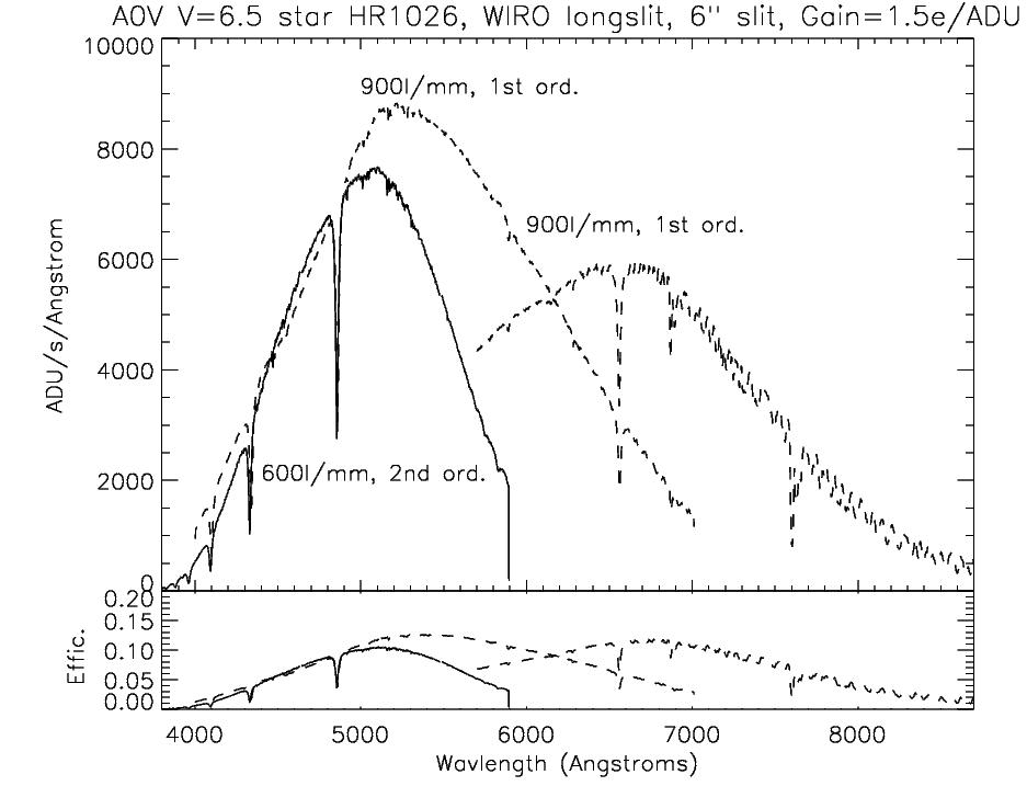
Sensitivity
Spectroscopy on targets brighter than about V=15 is feasible in reasonable
integration times. Fainter targets may be possible in excellent conditions
albeit with low S/N. The following plot shows count rates in ADU per second for a V=6.5 mag.
A0V star (HR1026) and total system efficiency assuming a gain of 1.5 e/ADU for two common grating setups.
The total efficiency involves losses for atmosphere, detector, mirrors and glasses in the 3 lenses, and a
small amount of slit loss.
 Order
Separation Filters
Order
Separation Filters
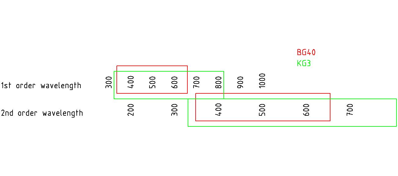
The use of order separation
filters is to prevent 1st order light from contaminating
the 2nd order. Of course, this is not a problem if using a
grating blazed for 1st order—in that case the goal
is to prevent 2nd order light from contaminating the 1st.
There are three available filters: BG40,
KG3,
GG455 (yellow glass, says 463 on edge)
although any 1” circular filter will fit in the slide. The BG40
will work well for any situation where you want to observe from
~350 nm to 600nm. Although since the instrument is not very UV
sensitive you won't get much at the blue end, also the BG40 starts
cutting-off steeply near 600 nm so H-alpha would be faint. The KG3
filter is wider however, if you want to work in the 400-800 nm range
in 1st or 2nd it will be fine
(remember the instrument wont let much light through before 400nm).
Unfortunately, the KG3 does allow some leaks, but if you are
observing far from the overlap, it won't matter. GG455 is used in conjunction with the
1800l/mm grating to prevent 2nd order contamination when working at red wavlengths longer than about 700 nm.
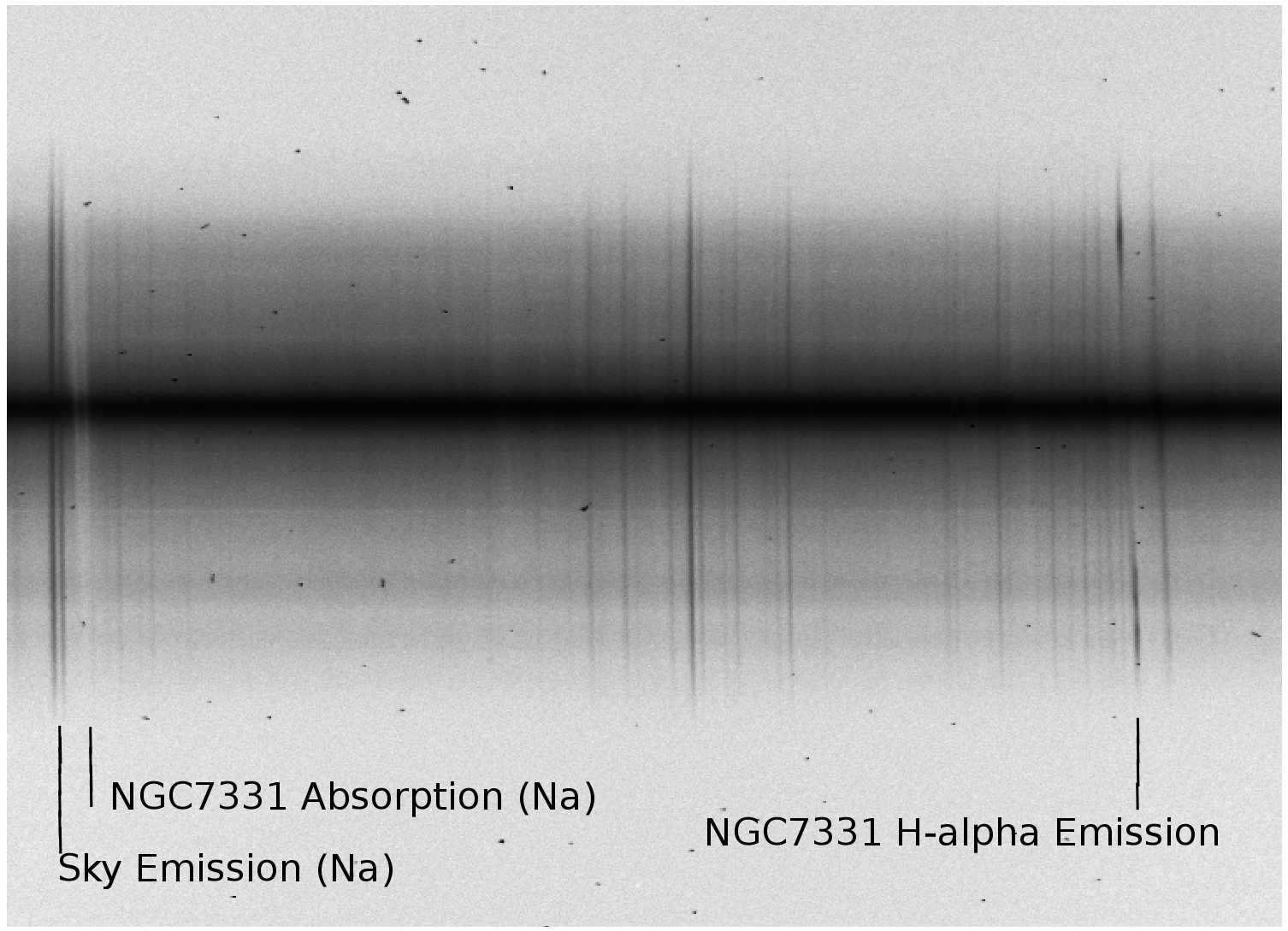
Longslit
Interface Sample
Spectra Last
Modified 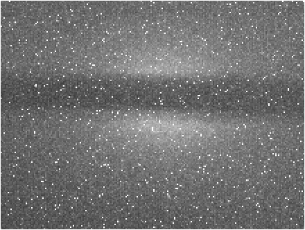 Guider
The
current guider in use is the SBIG ST-2000.
When used in the slit viewing mode the camera has a field of view of
approximately 25 arcseconds.
Nominally
the instrument is mounted at a position angle of zero degrees, in
which case the slit runs North-South. The instrument can be rotated
+/- 90 degrees.
The dome flat screen allows for taking
flat frames to get the illumination along the slit. Exposure times
will vary on the intensity of the flat lamps and on the slit width
and if a filter is being used. A typical situation is with a slit
width of 2.5arcseconds with a filter (~90%
throughput) and the lamps at 120V in
which case an exposure of 180s yields ~25,000 counts.
The Longslit interface controls one stepper motor on
the long slit spectrograph with .... to be written

Andy
Monson