WIRO-Spec: An Integral-Field, Volume-Phase Holographic Spectrograph
The Wyoming Infrared Observatory consists of an infrared-optimized 2.3-m telescope located on Jelm Mountain, about 25 miles south-west of Laramie, WY. This facility is currently one of the larger telescopes owned by a single university in the United States and is operated by the University of Wyoming . WIRO was completed in 1977 and was the first large, infrared-optimized telescope. In order to minimize the background at mid-infrared wavelengths the telescope was designed to be used at the Cassegrain focus with a relatively large f-number, f/27. But WIRO-Spec is an optical spectrograph with a CCD as the detector. The scale at the Cass. focus is about 3.3 arsec/mm and is thus poorly matched to the 13.5 mm pixels of the EEV/Marconi CCD. This means that the design of the spectrograph required careful consideration. Our goal was to develop a high-efficiency, integral-field spectrograph at minimum cost. The primary considerations were:
1) matching the diameters of the individual fibers to 2-pixel sampling on the CCD with a realistic reduction factor (< 5) for the spectrograph optics,
2) matching these fibers as closely as possible to the typical seeing at WIRO (thought to be about 1 arcsec),
3) maximizing the usable slit length in order to maximize the number of fibers in the array,
4) maximize the efficiency of the spectrograph by minimizing the vignetting losses,
5) acheiving a minimum resolution of 5000 at Ha ,
6) matching the reduction factor and camera focal length to available surplus optics.
The first consideration requires that the fibers must have a diameter less than about 130 mm (26 m m x 5). However, note that 130 mm fibers would be only about 0.4 arcsec at the Cass. focus of the telescope and so the second consideration requires some sort of re-imaging. One solution would be to place the fiber optic array behind an array of micro-lenses. However, this approach was considered too expensive given our limited budget. Instead, we chose to use a bare, hexagonally-packed fiber-optic array placed behind a focal-reducing lens. The packing fraction or filling factor with this approach is about 70%. We chose a comercially available Optec 0.33x focal reducer. This results in an f/9 input beam and a scale of 10 arcsec. This means that a standard-size, 100 mm fiber would subtend 1.0 arcsec on the sky. This choice results in a convenient reduction factor (< 4) for the fiber to be re-imaged onto the 13.5 mm pixels of the CCD with 2-pixel sampling. It must be acknowledged that optical fibers produce a "focal ratio degredation" in the sense that the output beam from the fiber will be faster than the input beam into the fiber. Although some testing suggests that an input beam of f/9 will result in an output beam as slow a f/7.5 this has not been our experience with comercially manufactured fiber optics. The output beam of our fiber is f/6.5. As a result, a reduction factor of 4 would requre a very fast, camera lens, < f/1.6.
The third and fourth consideratons require that the length of the collimated beam be kept to a minimium in order to avoid the vignetting losses that otherwise result from the off-axis fibers along the slit and the wavelength-dependent vignetting that can occur due to the dispersing element. In addition, the recent development of transmissive, volume-phase holographic gratings () allows very high efficiency gratings (> 80%) and very short collimated beams. Currently available VPH gratings have active regions with dimensions of 90 - 100 mm, comfortably larger than the apertures of typical, commercial camera lenses. Finally, if the focal plane of the slit assembly is plane to the optical axis, then the output beams of the fibers will be parallel to the optical axis (telecentric) and thus the fibers at the extreme ends of the slit can easily suffer from substantial vignetting losses. In order to avoid this, we chose to insert a positive field lens into the beam just behind the output of the fibers. Since this lens is very close to the "object plane" of the spectrograph, it has relatively little optical power and essentially "tilts" the output beams of each fiber as a function of height along the slit such that a "geometric pupil" can be formed where all the beams from each fiber cross. The focal length of this lens was chosen in order to place the geometric pupil on/near the input aperture of the spectrograph camera (see below).
The fifth consideration sets the focal length of the spectrograph camera. Since VPH gratings have a maximum efficiency when used at/near the Littrow condition the grating equation (for 1-st order) becomes:
nl = 2sina,
where n is the grating frequency (l/nm), l is the wavelength (nm), and a is the grating input/output angle.
Upon differentiation this becomes:
dl = cosad a/n (1).
Since position of any off-axis fiber in the image plane of the camera lens is given by arc-length formula:
s = fa,
where a is the off-axis angle of a particular fiber when viewed by the camera, s is corresponding off-axis distance in the image plane of the camera, and f is the focal length of the camera lens. Upon differentiating this becomes:
ds = fda (2).
When equations (1) and (2) are combined we obtain:
dl = cosads/f n.
Thus, if the available VPH gratings are limited to 1000 - 1500 l/mm we require a camera focal length of about 100 mm in order to achieve a minimum spectral resolution of 5000. Since the grating-camera angles will be 2a in a Littrow configuration we need to allow for a collimated beam length of about 150 mm with the available VPH gratings.
Finally, the sixth consideration required some compromise in the design of the spectrograph optics. First, commercial camera lenses with 100 mm focal length are not available any faster than f/1.8. The focal ratio degredation of the fibers (see above) means that we needed to consider reducing the reduction factor of the spectrograph optics somewhat to avoid vignetting by the camera aperture. In contrast, the collimator can be relatively slow provided it has a sufficiently large aperture such that the off-axis fibers will not be vigentted. An internet seach revealed a surplus aerial camera lens which was well-matched to the available camera lenses. For the camera we chose a Nikon 109mm f/1.8 lens and for the collimator we chose a Kodak/Ektar 345 mm f/3.5 lens.
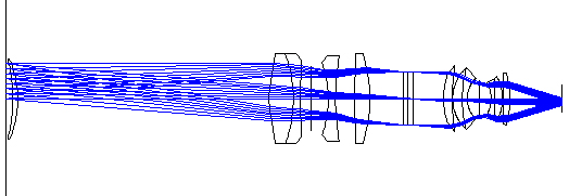
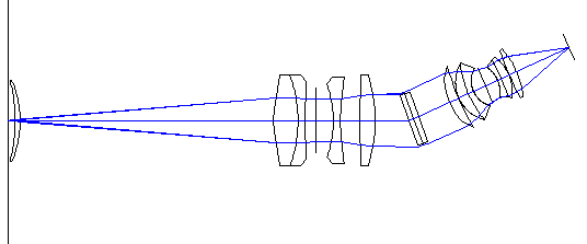
The figures below shows the optical design we adopted for WIRO_spec. The top figure shows a side view and the bottom figure shows a top view. The fiber-optic "slit" plane is represented by the vertical line at left. The output light cones are shown in blue. The first element is a meniscus field lens which deflects the light from off-axis fibers towards the optical axis forming a geometric pupil near the VPH grating (rectangular element in the center). The light from each cone then encounters the 4-element collimator (Tessar design). The length of the collimated beam is designed to be as small as possible to avoid vignetting but still leave sufficient room for the grating to be tilted to up to 45-degrees. The dispersed light then enters the camera (Double-Gauss design) which images the spectra onto the CCD, illustrated by the vertical line at right. The actual lens elements are only meant to be representative since the specifications for the surplus lenses were not available.
WIRO Spec: A Volume-Phase
Holographic Spectrograph
![]() Contact:
Contact:
Links to related sites