|
|
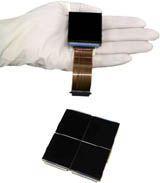
At the present time
the largest single near infrared detector arrays are the Hawaii-2
arrays made by Teledyne (formally Rockwell
Scientific). These detectors have 18.5 um pixels in a 2048x2048
array and are sensitive from a wavelength of 0.9 to 2.4 um. The
high cost of these arrays, approximately $350,000 a piece, severely
limits the number that can be purchased by a single university research
group. As a result, WWF-Cam has been designed around a single
array. This means that a large field of view can only be
accomplished by reimaging, with a corresponding reduction in the plate
scale of the instrument (see below). The image shows the Rockwell
Hawaii-2 array that will be incorporated into WWF-Cam. We will be
mounting the array on a fanout board provide by John Geary of Harvard
Smithsonian Observatory. This
board contains the basic components needed to drive the array.
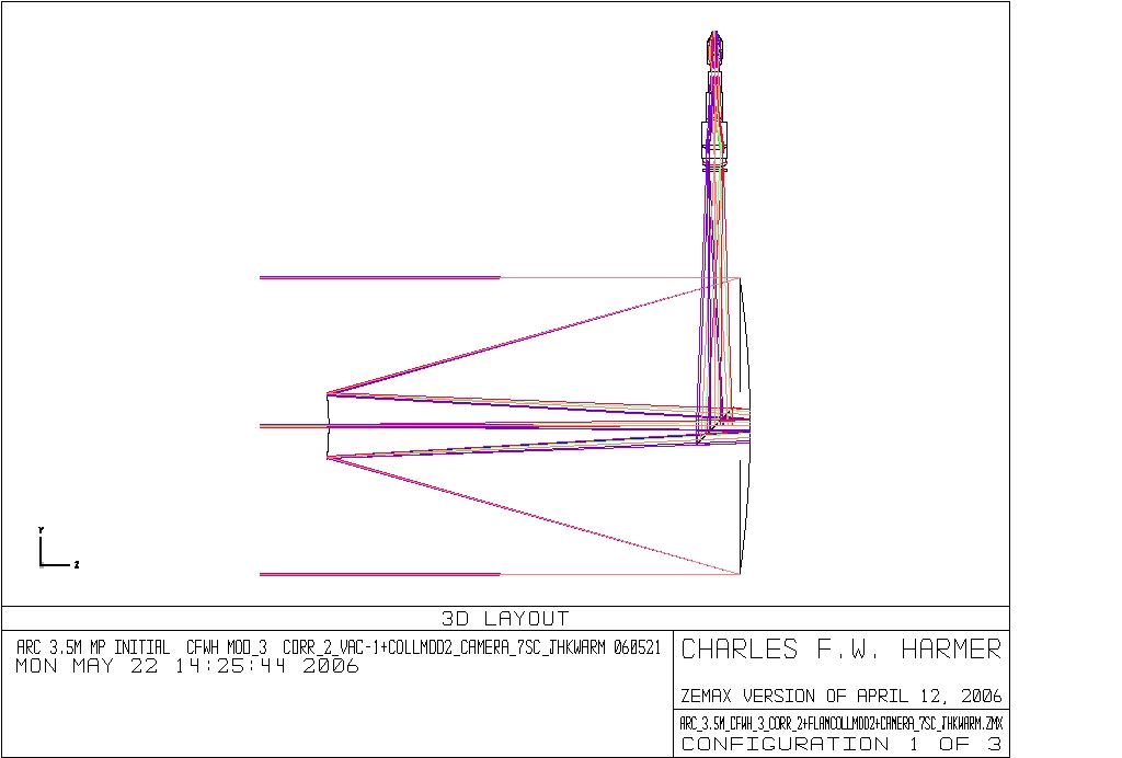
Optical Design
The design of WWF-Cam is based on a similar instrument known as
FLAMINGOS. FLAMINGOES was designed by Charles Harmer (NOAO) and
Richard Elston (Univ. of Florida). Since the development of this
instrument several similar instruments have built for various
telescopes around the world. Charles Harmer was kind enough to
rework his original design for FLAMINGOS for WWF-Cam. The major
challenge in the design of WWF-Cam was driven by the desire for the
highest practical reduction factor within the insturment such at that
WWF-Cam could be placed on a large telescope but still produce the
largest possible field of view. The APO 3.5-m telescope at Apache
Point is considered as the likely home of WWF-Cam. The resulting
design is shown in the figures below.
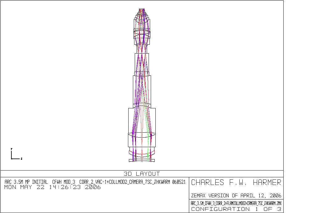
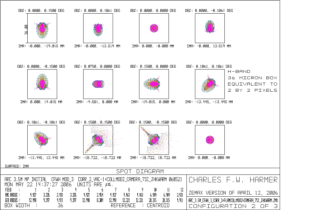
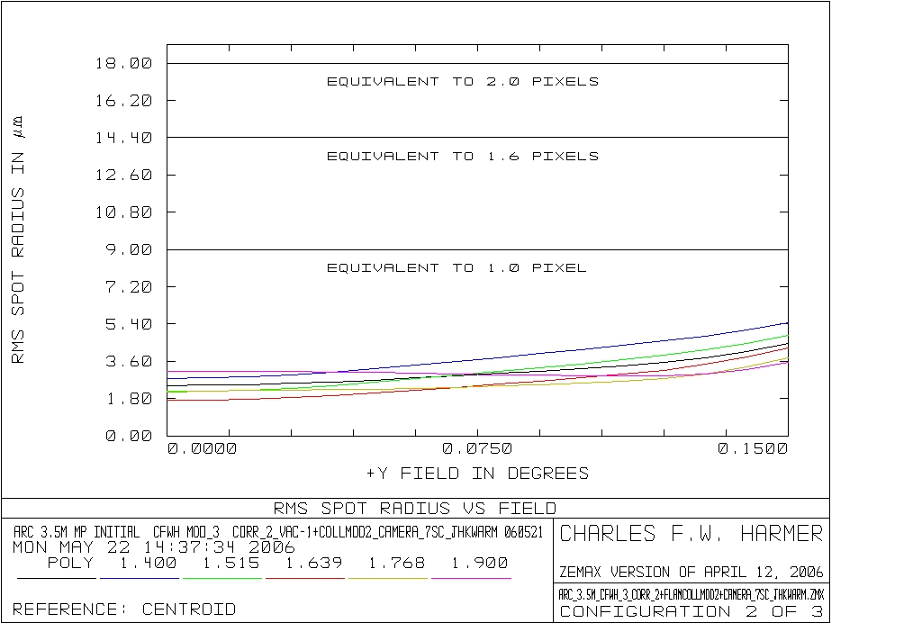
The requirement of a large field-of-view means that the design
for WWF-Cam is complex. However, the design should produce excellent
images over the full 17-arc min. field of view. The H-band spot
diagram and rms vs. field angle are shown below.
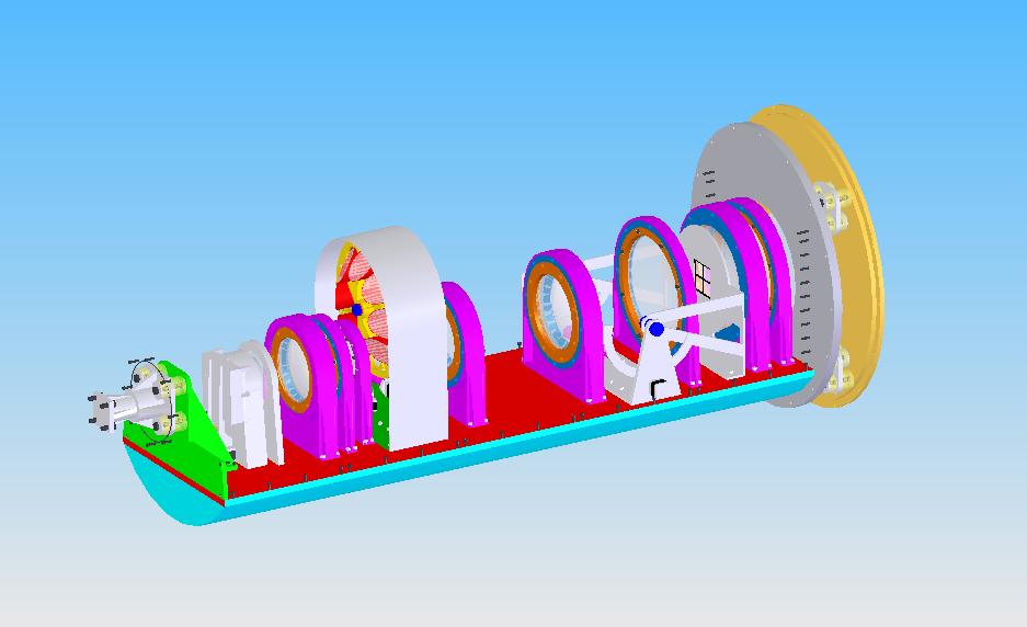
Preliminary Mechanical Design
The mechanical design of WWF-Cam will also be complex.
Since the
camera must operate at infrared wavelengths all the components must be
cooled to liquid nitrogen temperature (77 K) in order to minimize the
thermal background within the camera. However, since the camera
is
designed to produce the widest possible field it must be designed to be
as small as possible both to reduce weight, and hence flexure, as well
as to make it practical to cool to these low temperatures. The
figure below shows the design currently being considered for WWF-Cam.
|
|
Electronics & Software Design
The WWF-Cam electronics can be broadly classified into 3
groups: instrument control, array control, and system monitoring.
1) Instrument control
Control of the WWF-Cam instrument is done through cryogenic
stepper motors via a Compumoter 8-axis stepper motor controller, the
C6k8, from Parker
Automation. The C6k8 is fully programable and contains a
variety of inputs and outputs which are used to sense home/limits and
encoder inputs.
2) Electronics & Array Control
The focal plane array is controlled via a SDSU
Gen-II Controller designed and built by Bob Leach of Astronomical Research Cameras.
It also uses a set of pre-amp cards and co-adder boards from IR-Labs. The combination allows
the entire 2048x2048 Hawaii-II array to be read in about 0.1
second. The Gen-II controller is highly versatile. In particular,
custom waveforms for each detector array can be downloaded to the
controller using a computer interface. This allows for selectable
regions of interest, on-chip binning, etc. Initial tests and
characterization of the controller are now complete and we are
currently waiting on delivery of the focal plane array.
3) System Monitoring and Control
(this section under construction)
At the present time we are planning to use LABVIEW for software
control of the instrument. LABVIEW has been developed by National Instruments for use as
a hardware-control environment. It has been used extensively for
astronomical instrumentation.
4) Graphical User Interface (GUI)
(this section under construction)
5) Additional
Technical Documents
Here are links to more technical web pages (under
development):
Near-Infrared Sky
Cryogenic Test Dewar
Characterization of the SDSU Gen-II Controller
Mechanical Details