Overview
The WIRO Cassegrain GAM is used to acquire an astronomical target and
position it onto the fiber-optic integral-field unit (see figure below).
A motorized slide within the GAM enables the user to position one of three
pick-off mirrors into the beam. These include: 1) a solid mirror for
target acquisition, 2) a pelicle (92%/8%) beam splitter, and 3) a perforated
mirror for offset guiding while the light of the target goes to the
fiber-optic array. A small SBIG-237 CCD camera is mounted on an x-y
stage on the side of the GAM and can be used to either acquire the target
object using the solid mirror or for guiding with either the pelicle or the
perforated mirror. A calibration asembly is mounted opposite the guide
camera such that light from the calibration lamps is imaged onto the fiber
array via a small mirror cemented onto the back side of the larger solid
mirror. The fiber optic array is located beneath the 3-mirror stage
and can be rotated to any desired position angle. Both the fiber optic
array and the guide camera are located behind a 0.33X focal reducers such
that the 100 um fibers of the array correspond to 1.0 arcsec on the sky.
The right-hand figure shows the fiber-optic array viewed through the focal
reducer. The resulting scale is 9.96 "/mm corresponding to 0.07
arcsec/pixel and a field of view of 46 X 34 arcsec with the ST-237 CCD.
However, the GAM x-y stage (see figure) has a range of +- 50 mm such that
the searchable field with the GAM is a little over 17 arcmin on a side.
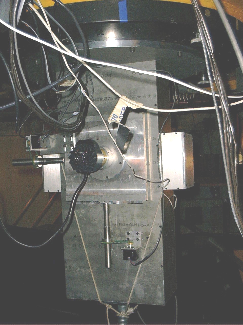
Mechanical Design
The motorized, 3-mirror slide of the GAM is designed around 2 precision, linear slides manufactured by Velmex Inc. The x-y stage and the GAM superstructure were designed by Mike Pierce and Phillip Haynes of the UW Physics and Astronomy Department with help from Steve Hodder of the A&S machine shop. Steve was also the chief machinist for the project. The electrical cabling was done by James Weger of the Physics and Astronomy Dept. The figure below at left shows the mechanical layout of the GAM. The figure below at right shows a close-up of the 3-mirror slide.
Once the telescope is positioned to the coordinates of a target the final positioning is done using the SBIG-237 camera. This is typically done using the #1 (solid) mirror using a series of exposures to determine the position of the target and then determining the offset necessary to place the target onto the center of the fiber optic array. Once the telescope is positioned, the GAM slide is positioned to bring the #3 mirror (with the central hole) into position such that the light from the target reaches the fiber optic array. In this configuration the light from the surrounding region is diverted to the ST-237. The x-y stage can then be moved in a "cruise mode" (see below) until a suitable guide star can be found and guiding begun. Alternatively, the GAM stage can be positioned to the #2 position (the 92%/8% pelicle) and the guiding can be acomplished using the object itself provided it is sufficiently bright.
The integral-field, fiber optic array is mounted on a rotational stage located below the 3-mirror slide and behind a 0.33X focal reducer. The position-angle of the array can be chosen if desired and positioned accordingly.
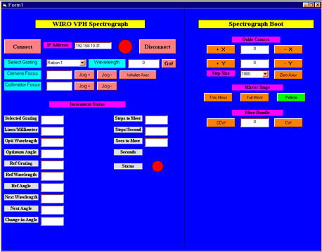
User Interface
The graphical user interface (GUI) was designed and programed under Visual Basic 6 by M. Pierce and P. Haynes. The interface communicates over ethernet to a Compumotor 6K8 stepper motor controller. The figure below shows the GAM GUI. The left-hand portion of the GUI is associated with the GAM and the right-hand portion of the GUI is associated with WIRO-spec, the optical VPH spectrograph.
The top-most text box shows the IP address of the 6K8 controller. The next set of buttons are used to connect/disconnect to/from the CK8. The right (GAM) side has buttons for "jogging" the X-Y stage and a text box is included for setting the default step size. At present 10,000 steps corresponds to roughly 10 arcsec. To the right of text box is a button for bringing the X-Y stage back to 0,0. This is essential for acquiring the next target since otherwise the ST-237 will not be aligned with the fiber optic array.
The next set of three buttons allow the GAM mirror stage to positioned to one of the three positions. Note that the current position is highlighted in green. Below that are two buttons that allow the fiber optic array position angle to be set to any desired position.
Three-Position Mirror
The three-position stage is positioned using the buttons on the GAM interface. Note that the light from an object only reaches the fiber-optic array using the "full" or "pelicle" positions and that calibration exposures can only be taken with the mirror stage in the "full" position. The latter position allows the light from the calibration lamps to be reflected off of a small mirror mounted on the back of the full mirror and then onto the fiber optic array. If the target is sufficiently bright, guiding can be acomplished using the light from the object itself via the "pelicle" position. However, it is expected that in most cases the object will be sufficiently faint that this will not be possible and a suitable, nearby guide star will be needed. In this case, the object exposure will be acquired with the "thru" mirror and the x-y stage positioned such that a suitable guide star for the ST-237 can be found. Note, before moving to the next program object, be sure to move back to the "full" mirror or it may be very difficult to locate the object since the light will now be going to the optical fiber.
X-Y Stage
The guide camera consists of an SBIG ST-237 CCD camera. The camera is located behind a second 0.33x focal reducer which produces a scale of 9.96 arcsec/mm. The 7 um pixels of the ST-237 are thus 0.07 arcsec and the field of view is approximately 46 X 34 arcsec. However, the range of the x-y stage is +- 50 mm giving a searchable field of nearly 19 arc minutes. The step size of the x-y stage motions can be adjusted by the user but the default of 10000 steps corresponds to about 10 arcsec. Note that a +x motion moves the stage East (the star West) while a +y motion moves the stage North (the star South). The ST-237 is operated in a "guide mode" using a commercial software package (Maxim DL) which provides a guide signal based upon centroiding of the stellar image. The guide signal consists of four simple TTL signals representing +- x-y offsets which are then fed to the WIRO control system via the hand-panel input (see below).
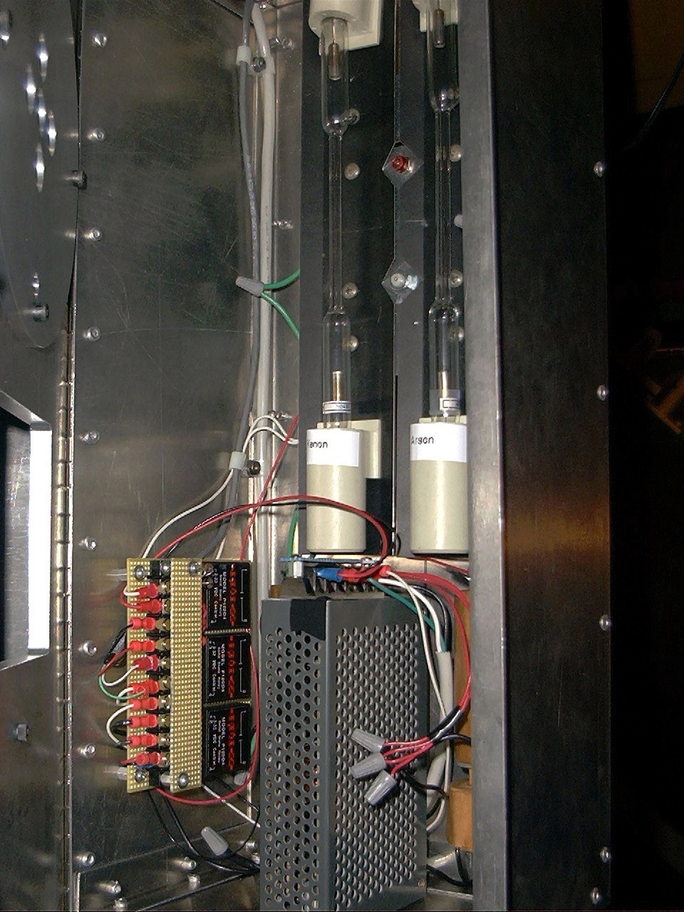
Using the GAM Calibration Lamps
The calibration lamps are contained within a light-tight housing mounted on the "back-side" of the GAM (opposite of the ST-237 CCD). The currently available lamps include Ne, Ar, and Xe discharge lamps as well as a flat-field continuum source. These are projected onto the fiber-optic array using a set of lenses and a small mirror mounted on the rear of the solid mirror. As a result, the solid mirror position must be selected from the GAM interface in order to use the calibration lamps. The desired lamp can be selected using the buttons on the GAM interface. The figure below shows the open calibration housing.
1) When ready to take a comparision exposure begin by selecting the GAM "full mirror" .
2) Select the desired calibration lamp using the appropriate buttons on the GAM interface.
3) Take an exposure with WIRO-Spec and adjust the exposure time as necessary.
4) When finished, be sure to turn off the calibration lamp before taking any data!
Calibrating the GAM X-Y Stage
At the beginning of each night the user must verify that the X-Y stage is calibrated in order to accurately position objects onto the fiber-optic array.
1) Verify that the x-y stage is positioned to x=0, y=0. This is necessary so that when the telescope is positioned such that the light from a target falls on the fiber-optic array its light will fall at a particular location with the ST-237 field (and vice versa).
2) During twilight, position the telescope to a resonably bright star (V ~ 5 mag.) in order to align the ST-237 with the fiber optic array,
2) With the GAM mirror positioned to the "pelicle" position, use the Maxim DL software to take a 1-sec. exposure (the "expose" tab),
3) Repeat as necessary while offsetting the telescope until the star is close to x = 333, y = 258 on the ST-237 CCD (the X-Y stage must be at 0,0),
4) Now take a short exposure with WIRO-Spec and verify that most of the light is going down fiber #152 (EEV/Marconni column #1151),
5) Peak up on the star by making small offsets (~0.3 arcsec) until the star is centered on fiber #152,
6) Finally, take another exposure with the ST-237 in order to measure and record the x-y position of the star. After this point, any object can be positioned on fiber #152 by offseting the telescope such that it appears at the corresponding x-y position within the ST-237 image.
Guiding with the GAM
Once the object is positioned onto the optical fiber and the mirror stage is positioned in the "thru" position the user is ready to locate a suitable guide star. The procedure is as follows:
1) If a guide star has been previously selected then the x-y stage can be positioned to the appropriate position. The default step size of 10000 steps corresponds to about 10 arcsec with a motion in the +x direction corresponding to East (the star moves West) and +y corresponding to moving the stage North (the star moves South).
2) If the user needs to find a guide star then the x-y stage can be operated in a "cruise" mode. Use the x-y buttons on the GAM interface to search the vacinity of the target while taking exposures with the ST-237. Try to find a resonably bright star such that expsoures will be less than a minute or two.
3) Once a suitable guide star is found select the "guide" mode with an exposure of at least 10 sec. Be sure to enter the declination of the guide star.
5) Once a full frame is taken, position the centroiding box on the selected star and hit "start" to begin guiding.
6) Verify that the guiding is satisfactory and then begin the object exposure with WIRO-Spec.
For more details see Guiding with the ST-237
.
Users Manual
Last Modified 9/10/2002 by Michael Pierce (mpierce@uwyo.edu)