NIIS Electronics
GUMP Preamplifier
The General Use Multi-channal Preamp (GUMP), provided by Infrared Labratories, Inc., is used as the preamplifier
needed by the Leach controller. The Gump consists of a mainboard and four daughter boards. The GUMP has its own power supply which sits externally to the preamplifier itself and the controller
(pictures of the power supply).
 The mainboard provides the connections to all four daughter boards,the
power supply,the connections to the leach Controller and the circular
connector which goes directly to the array inside the instrument.
Connected to the mainboard is the GUMP end panel,which corresponds to
the black end of the box shown in the GUMP pictures. This panel is
where the connectors to the Leach controller and the power supply enter
the GUMP.
The mainboard provides the connections to all four daughter boards,the
power supply,the connections to the leach Controller and the circular
connector which goes directly to the array inside the instrument.
Connected to the mainboard is the GUMP end panel,which corresponds to
the black end of the box shown in the GUMP pictures. This panel is
where the connectors to the Leach controller and the power supply enter
the GUMP.
 As
is stated on the Leach Controller page, the information produced from
the array inside the instrument first travels through the GUMP via the
mainboard, then uses the daughter boards to vary the voltages and gains
before the information is sent to the Leach controller. The daughter
boards connect “vertically” into the four parallel connector slots
shown on the mainboard. Detailed circuit diagrams for the daughter
boards, as well as for the mainboard can be found in the following PDF
document: GUMP.pdf
As
is stated on the Leach Controller page, the information produced from
the array inside the instrument first travels through the GUMP via the
mainboard, then uses the daughter boards to vary the voltages and gains
before the information is sent to the Leach controller. The daughter
boards connect “vertically” into the four parallel connector slots
shown on the mainboard. Detailed circuit diagrams for the daughter
boards, as well as for the mainboard can be found in the following PDF
document: GUMP.pdf
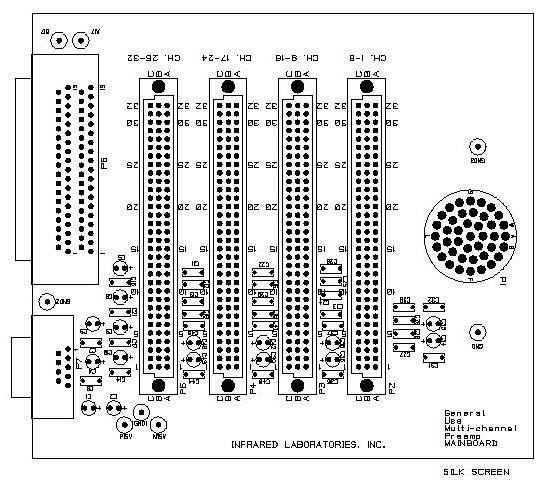
Mainboard
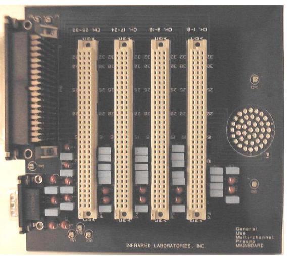
Left: Picture of the Mainboard without the daughter boards
Right: Diagram of the Mainboard (click for a larger image)
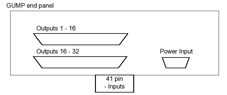
End panel: connects mainboard with the power supply and Leach controller
| Quantity | Description |
|---|---|
| 1 | connector, 41 PIN Bulkhead Recepticle |
| 1 | connector, D-SUB 9 pin male right angle, PCB mount |
| 1 | connector, DUAL DSUB 37 pin male right angle, PCB mount |
| 1 | enclosure, Lansing box |
| 3 | connector, D-SUB mounting Hardware kit |
| 16 | capacitors, 10 UF/25 VOLT |
| 30 | capacitors, 0.1 UF caps |
| 8 | connectors, Header pins, Breakaway type |
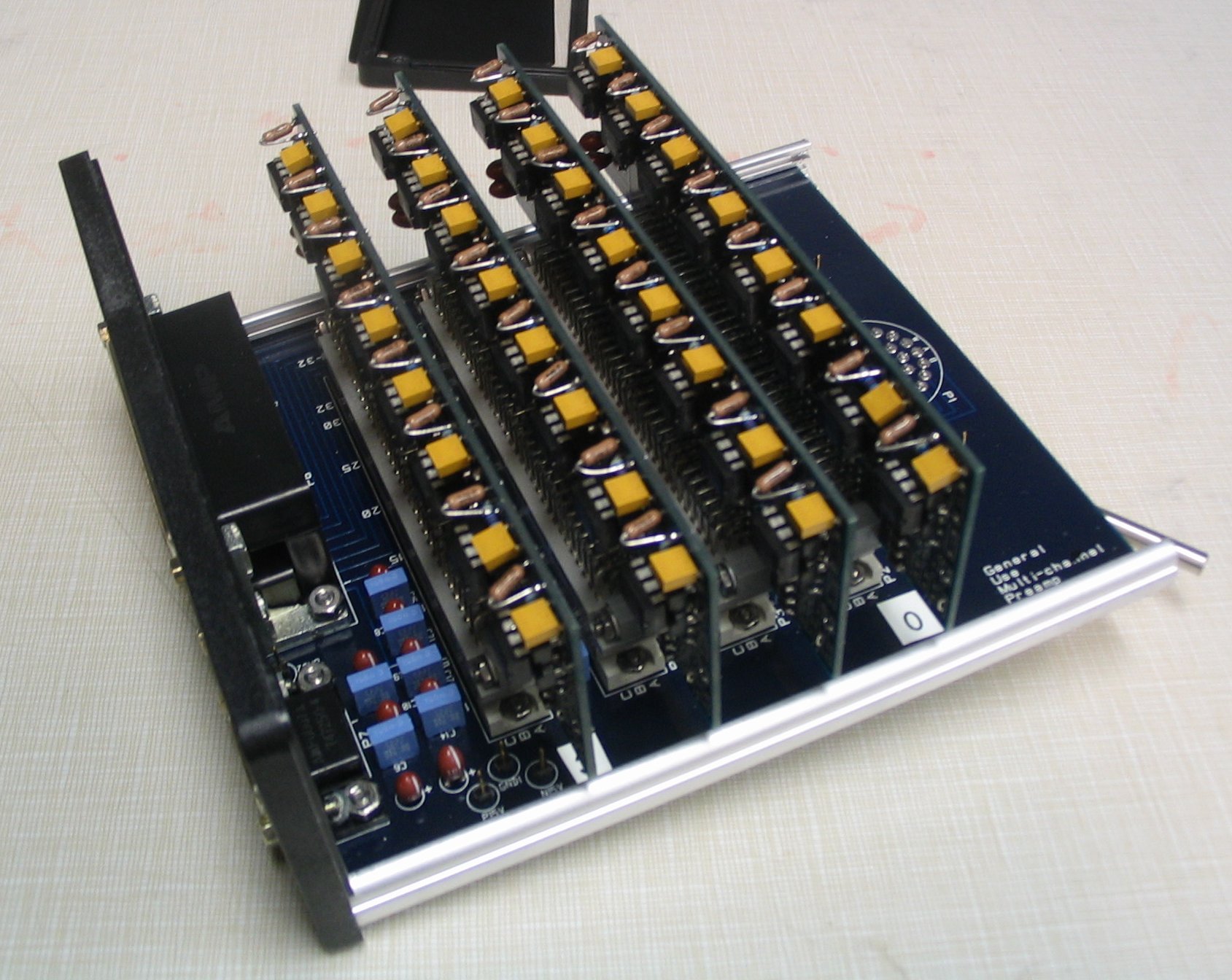
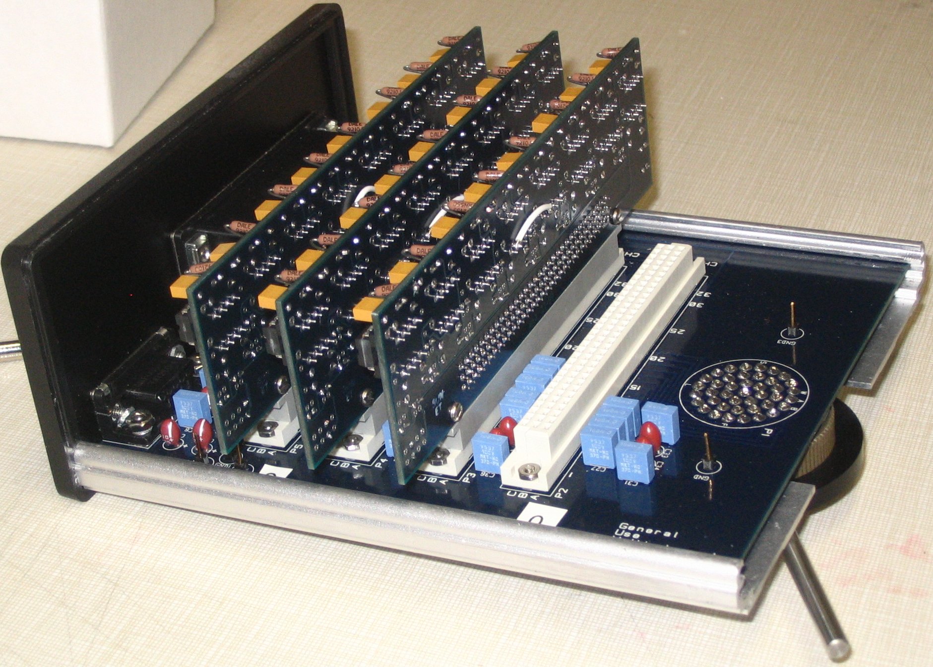
Daughter Boards
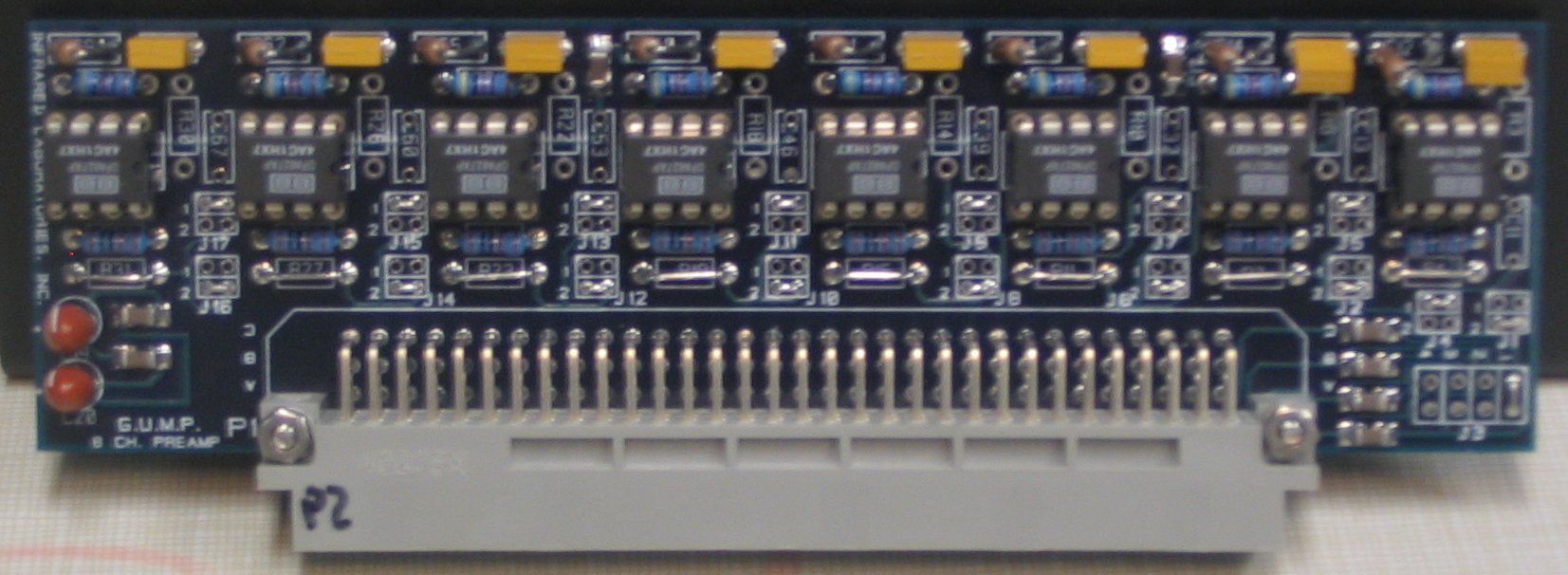
Picture of one of the daughter boards
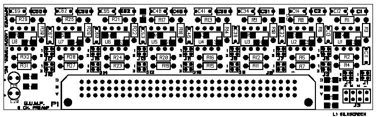
Diagram of a daughter board, notice that it corresponds to the image above
Parts List:
| Channel Components | Channel 1 | Channel 2 | Channel 3 | Channel 4 | Channel 5 | Channel 6 | Channel 7 | Channel 8 |
|---|---|---|---|---|---|---|---|---|
| 0.1 UF - SM 25V | C3, C4 | C5, C6 | C36, C35 | C43, C42 | C50, C49 | C57, C56 | C64, C63 | C71, C70 |
| 68 PF | C1 | C2 | C31 | C38 | C45 | C52 | C59 | C66 |
| 4 kΩ | R1 | R8 | R9 | R13 | R17 | R21 | R25 | R29 |
| 8 pin OP Amp socket | U1 | U2 | U3 | U4 | U5 | U6 | U7 | U8 |
| 1 kΩ | R2 | R5 | R12 | R16 | R20 | R24 | R28 | R32 |
| jumper | R4 | R7 | R11 | R15 | R19 | R23 | R27 | R31 |
| jumper | J1, 2-4 | J2, 2-4 | J6, 2-4 | J8, 2-4 | J10, 2-4 | J12, 2-4 | J14, 2-4 | J16, 2-4 |
| jumper | J4, 1-3 | J4, 1-3 | J4, 1-3 | J4, 1-3 | J4, 1-3 | J4, 1-3 | J4, 1-3 | J4, 1-3 |
| open | R3 | R6 | R10 | R14 | R18 | R22 | R26 | R30 |
| open | C11 | C13 | C32 | C39 | C46 | C53 | C60 | C67 |
| 10 kΩ | C12 | C14 | C34 | C41 | C48 | C55 | C62 | C69 |
| OPA 627 AP | U1 | U2 | U3 | U4 | U5 | U6 | U7 | U8 |
Power Supply Components
| 0.1 UF - SM 25V | C15, C16, C7, C18 |
| 10 UF, 25 Volt | C19, C20 |
Voltage Offset Components
| 0.1 UF - SM 25V | C23, C24, C25, C26 |
| jumper (J3) | pins 1-5, applied to channels 1 thru 8 |
Board Connector
| 96 pin IDC, right angle |